
Overview of CSI Bridge Advanced 26.3.0.3324:

Designing a bridge is no small task. From handling complex geometry to ensuring structural safety and performance, engineers face countless challenges. That’s where CSI Bridge Advanced 26.3.0.3324 Crack steps in.
CSI Bridge Advanced 26.3.0.3324 Full Version is an engineering software application dedicated to the design, modeling, and analysis of bridges. Unlike general structural design tools, it is tailored to meet the unique demands of bridge projects—whether it’s a short-span highway bridge, a cable-stayed bridge, or a large suspension structure.
The software offers a fully integrated environment where modeling, analysis, and design are combined in one workflow. This makes the process smoother and helps engineers save time without compromising on precision.
CSI Bridge Advanced 26.3.0.3324 Key Features:
User Interface:
- Completely Customizable Graphical User Interface
CSI Bridge Advanced 26.3.0.3324 License Key offers a single-user interface for modeling, analysis, design, planning, load estimation, and reporting.
- Smooth DirectX Graphics
The DirectX graphics mode has now been enhanced to use DirectX 11 for improved speed and features. DirectX 11 graphics provide fast model navigation and fast rotation.
- Multiple Views on a Single Screen
You can view moment diagrams, load assignments, rejected forms, project outputs, and reports on one screen. The new display allows you to display all loads within the same load scheme, for all types of objects, on one display.
- Advanced Shortcut Tools
Shortcut keys are implemented in the menu interface, including the hotkey setting. Several Edit, Assign, and Select menu forms have been improved so that they can remain open for reuse with the Apply button.
- Floating Forms
The destination and selection menu forms have been improved so that they can remain open for reuse.
Modeling:
- Adaptable Modeling Tools to Create Many Types of Bridges
Bridge models are defined parametrically using common bridge design terms such as layout lines, spans, supports, buttresses, bends, hinges, and subsequent tension. The parametric model is controlled through the bridge object model. The bridge object model is a set of finite element components that make up the entire analytical model, including deck sections, diaphragms, bearings, restraints, foundation springs, superstructure options, supports, bends, hinges, tension schemes, and more. Bridge models can be analyzed using either a 3D refined model or a 2D simple model.
- Wide Selection of Templates for Rapid Model Generation
CSI Bridge Advanced 26.3.0.3324 Keygen offers a convenient and fast approach to modeling bridges using Quick Bridge templates. They provide an excellent starting point for a model that can then be modified as needed.
- Interactive Database Editing
Interactive database editing allows you to edit model data in a table format, making it easier to make changes to the model. Tables are easy to export and import from Microsoft Excel and Microsoft Access.
- Automatic Section Cut Generation
Sections are created for the entire deck of the bridge, as well as for individual beams at each point of the station. Station points can be defined by the user.
Parametric Bridge Modeling:
- Bridge Wizard
The Bridge Wizard is a powerful tool that guides you step by step through the creation of a complete bridge model, with instructions for each step to ensure that all required components are defined in the model.
- Layout Lines
Marking lines determine the location of the carriageway of the bridge. They can be defined in CSiBridge using azimuth and station designations or PI inputs (points of intersection). They can be imported using a LANDXML file. As the layout lines change, the entire bridge structure and its parametric geometry are updated.
- Superstructure Deck Section Templates
CSI Bridge Advanced offers a wide range of parametric deck sections, including concrete box beams, precast I-beams, U-beams, steel I-beams, U-beams, and more. All deck sections can be parametrically configured to create a precise bridge deck section definition.
- Substructure
Bridge substructures can be modeled very accurately in CSiBridge, including bends, supports, restraints, bearings, and foundations. Foundation springs can be defined as 6X6 coupled springs or P-Y springs and applied to various foundation elements. Foundation springs can be modeled using linear or non-linear links.
- Diaphragms
Diaphragms can be located on supports and long spans. Types include concrete, steel beam, and detailed steel cross frames. They can be skewed and staggered. Internal cross frames for steel U-beams may also be specified.
- Parametric Variations
Changes in deck section dimensions, which include spacing between beams, deck and lip widths, depth, and more, can be applied to the bridge model using parametric variations. Parametric determination of variations significantly reduces bridge modeling time.
- Post-Tensioning
Set post-tension in CSiBridge using advanced tendon placement and force options. When defining box beams, CSiBridge will automatically assign drapery locations within the reinforcement, or the engineer can also edit them. Tendons can be fully automatically generated for segmental bridges.
- Lanes
Quickly identify lanes based on bridge layout lines. Bands can be defined as fixed or floating bands. The most important responsibility for each element in the bridge model is created using influence lines or surfaces.
Structural Components:
- Manage Joints, Frame, and Solid Elements with ease
CSI Bridge automatically creates connections at the intersections of structural objects or internal connections when building a grid of structural objects. Shared coordinates, destinations, and offsets can be displayed on the screen or in tabular format.
- Beams / Columns
The frame element uses a common 3D beam-column formula that includes the effects of biaxial bending, torsion, axial deformation, and biaxial shear. CSiBridge has a built-in library of standard concrete, steel, and composite section properties that meet US and international standards.
- Non-Prismatic Sections
Even non-prismatic and composite steel profiles can be easily defined. Sections of steel H-beams and U-beams can be easily defined using the steel beam editor form.
- Section Designer
Section Designer is an integrated utility built into SAP2000, CSiBridge, and ETABS that allows you to model and analyze custom cross-sections. The Section Builder is useful for evaluating bar properties and non-linear responses, including the behavior of the non-linear hinge and the PMM hinge.
- Shells
A shell element is a type of area object that is used to model the behavior of membranes, plates, and shells in 2D and 3D structures. The shell material may be homogeneous or multi-layered; material non-linearity can also be taken into account when using a layered shell.
- Cable Element
The rope element is a highly non-linear element used to simulate the behavior of a contact network of thin cables under its own weight. Tensile stiffness and large deflection non-linearity are inherently included in the formulation.
- Tendon Element
Tendons are easily drawn as independent objects with geometry defined as straight lines, parabolas, circular curves, or other arbitrary shapes. Tendon loads, including all losses, are easily determined in CSiBridge. Stresses can also be added to bridge spans and beams using template profiles that can be easily edited. Tendons can be considered elements or loads.
- Solid Element
A solid element is an eight-node element for modeling 3D structures and solids. It is based on an isoparametric formulation that includes nine optional incompatible bending modes and is useful for modeling objects where load, boundary conditions, section properties, or reactions are thickness dependent.
- Link Element
A link element can exhibit up to three different types of behavior: linear, non-linear, and frequency dependent, depending on the types of properties assigned to the element and the type of analysis being performed. The following link elements are available in CSiBridge: linear, polylinear elastic, multilinear plastic, gaps, hooks, dampers, friction insulators, rubber insulators, thermal isolators, frequency-dependent springs, and frequency-dependent dampers.
- Springs
Spring supports are connectors that are used to connect connections to the earth or other connections. They may be linear or non-linear. Non-linear reference conditions can be modeled, including gaps (compression only), multi-linear elastic or plastic springs, viscous dampers, and base insulators.
- Hinges
Loop properties can be created and applied to perform non-linear time history analysis in CSiBridge. Non-linear material behavior in frame elements (beam/column/brace) can be modeled using fiber hinges. This approach presents the material in cross-section as discrete points, each corresponding to the exact stress-strain curves of the material. Mixed materials, such as reinforced concrete and complex shapes, can be represented.
Loading:
- Increase productivity with the use of Auto Loadings
CSI Bridge Advanced Patch will automatically generate and apply seismic and wind loads based on various national and international codes. CSiBridge also has a sophisticated moving load generator that allows you to apply moving loads to tracks.
- Seismic
CSiBridge will automatically generate seismic survey requirements and compare these requirements with participants’ capabilities when the automatic seismic design is activated. Bearing displacements can be calculated using design analysis for bridges having a design seismic category D.
- Wind
CSI Bridge Advanced Crack will automatically generate and apply wind loads based on various national and international regulations. Wind loads can also be set by the user.
- Moving Loads
Moving loads can be applied to fixed or floating lanes to determine the maximum response to each bridge element. Moving loads can be applied using vehicle classes or individual vehicles.
- Define a wide array of loading conditions with the User Loads application
Define specific loads for the model using a wide range of load conditions with CSiBridge’s built-in custom load options. Loads can also be applied parametrically in the form of point, line, area, and wet concrete loads.
- Force / Moment
Force loading is used to apply concentrated forces and moments at joints and along frame members. This includes distributed and trapezoidal loads. Values can be specified in a fixed coordinate system (global or alternate coordinates) or a shared local coordinate system.
- Displacement
Displacement loading is the effect of bearing settlement and other external structural movements. The shear load can act through restraints as well as linear and non-linear spring supports. Multi-support dynamic excitation can also be considered for structures.
- Temperature
Thermal loading creates thermal deformation in the frame element. This deformation is determined by the product of the thermal expansion coefficient of the material and the temperature change of the element. All specified temperature loads represent the change in temperature from an unstressed state for a linear analysis or from a previous temperature in a non-linear analysis. Temperature loads can also be applied in the form of temperature gradients.
Analysis:
- CSiBridge handles numerous types of analyses
CSiBridge loading options include static, staged design, multi-stage static, modal, response spectrum, time (response) history, moving load, buckling, steady state, and more.
- Moving Loads – Static
Apply loads by specifying one or more lanes that a class of vehicles can operate in. Each permutation of vehicle classes operating in the lanes assigned in the load case will be taken into account in the analysis.
- Moving Loads – Dynamic
Multiple instances of the same vehicle operating on the same lane or rail track can be combined into a multi-stage load pattern, allowing complex load patterns to be used. For each instance, the vehicle can move forward or backward with a specified start location, start time, and speed.
- Many powerful dynamic analysis tools are available for both linear and nonlinear analysis
CSiBridge’s dynamic analysis capabilities include the calculation of vibration modes using Ritz vectors or eigenvectors, response spectrum analysis, and timing analysis for both linear and non-linear behavior.
- Response Spectrum
Analysis of the response spectrum determines the statistically likely response of a structure to a seismic load. This linear type of analysis uses response spectrum ground acceleration records based on seismic loading and site conditions rather than ground motion records over time. This method is extremely efficient and takes into account the dynamic behavior of the structure.
- Time History
Time dynamics analysis captures the step-by-step response of structures to seismic ground motions and other types of loading, such as blast, machinery, wind, waves, etc. The analysis can use either modal superposition or direct integration methods, and both can be linear or non-linear.
- Nonlinear Buckling
When calculating the non-linear static buckling, the total load is applied gradually. Stiffness and response are evaluated at each increment. Between each displacement step, the stiffness may change due to P-delta, large displacement, and/or the effects of non-linear material behavior. Since the buckling analysis takes into account the non-linearity of the material in shaping the buckling response, the results are often more realistic than those from the linear buckling analysis.
- P-Delta
P-delta analysis captures the softening effect of compression and the firming effect of stretching. Single P-delta analysis under gravity and continuous loads can be used to change the stiffness for linear load cases, which can then be superimposed on each other. Alternatively, each load combination can be analyzed for full non-linear P-delta effects. P-delta effects are included for all elements and are easily integrated into analysis and design.
- Direct-Integration Time History
The non-linear modal method, also called FNA for fast non-linear analysis, is extremely efficient and accurate for a wide range of problems. The direct integration method is even more general and can handle large deformations and other non-linear behavior. The non-linear time analysis can be combined with other non-linear cases (including staged building) for a wide range of applications.
- Buckling
Linear (bifurcation) forms of structural buckling can be detected for any set of loads. The buckling can be calculated from a non-linear state or a staged construction state. A full non-linear buckling analysis is also available, taking into account P-delta or large deflection effects. The through-circuit buckling behavior can be captured using static analysis with bias control. Dynamic analysis can be used to model more complex forms of buckling, such as pusher loading problems.
- Staged Construction
Staged construction is a type of non-linear analysis in the CSI Bridge Advanced that allows you to define a sequence of stages in which you can add or remove parts of a structure, selectively apply loads to parts of a structure, and take into account time-dependent material behavior such as aging. , creep, and shrinkage.
- Staged Construction Stages
Staged construction is variously known as phased construction, sequential construction, or segment construction, which can be used to add, remove, or age different parts of a structure.
- Creep and Shrinkage
Long-term deviations due to creep and shrinkage can be calculated along with a step-by-step design analysis. Time-dependent material properties are based on CEB FIP, ACI 209R, Eurocode, and other codes or user-defined creep curves.
- Static Pushover
The pushover analysis features in CSiBridge include an implementation of ASCE 41, AASHTO/Caltrans, and a variant of hinge and hinge based on stress-strain.
- Nonlinear Layered Shell
The non-linear layered shell element allows the plastic behavior of concrete walls, slabs, steel plates, and other area finite elements to be taken into account when calculating the initial level. Force-strain dependencies are determined for steel and concrete hinges.
- Dynamic
CSiBridge’s dynamic analysis capabilities include the calculation of vibration modes using Ritz vectors or eigenvectors, response spectrum analysis, and timing analysis for both linear and non-linear behavior.
- Modal
Modal eigenvector analysis finds structure eigenmodes that can be used to understand structure behavior and also as a basis for modal superposition in load cases with response spectrum and modal timing. Ritz vector-based modal analysis finds optimal modes for capturing structural behavior in load cases over response spectrum and modal versus time, and is more efficient for this purpose than eigenvector-based analysis.
You can also like CSI SAP2000 Ultimate + Crack
What’s new in CSI Bridge Advanced 26.3.0.3324?
(Released on 01-09-2025)
- Bridge Modeler
Geometry control is now available for the construction of balanced-cantilever segmental bridges.
- Bridge Design and Rating
Bridge rating for legacy bridges according to AASHTO MBE Section 6, Part B, along with resistance calculated based on AASHTO 17th Edition, 2002 is now available.
- Loading
Multi-step moving-load analysis has been enhanced to now include horizontal loads.
- Cloud Sign-in Licensing
Sign-in licensing now uses the system browser for a smoother authentication experience. Remote checkout licensing has also been added for dark site or air-gapped machines that do not have internet access.
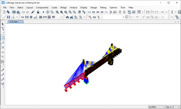
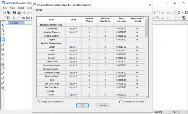
Screenshots:
System Requirements:
- Operating System: Windows 7/8/10
- Processor: Pentium IV or higher
- RAM: 2 GB RAM (4 GB recommended)
Hard Disk Space: 200 MB or more
CSI Bridge Advanced 26.3.0.3324 Crack Full Version Download from the link given below: